- 您现在的位置:买卖IC网 > Sheet目录1062 > 101-0954 (Rabbit Semiconductor)KIT DEV RABBIT RCM3360/3370 INTL
�� �
�
�2.2� Hardware� Connections�
�There� are� three� steps� to� connecting� the� Prototyping� Board� for� use� with� Dynamic� C� and� the�
�sample� programs:�
�1.� Attach� the� RCM3360/RCM3370� module� to� the� Prototyping� Board.�
�2.� Connect� the� programming� cable� between� the� RCM3360/RCM3370� and� the� workstation�
�PC.�
�3.� Connect� the� power� supply� to� the� Prototyping� Board.�
�2.2.1� Attach� Module� to� Prototyping� Board�
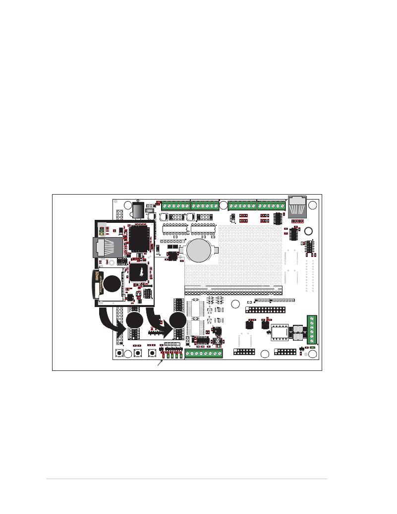
�Turn� the� RCM3360/RCM3370� module� so� that� the� Ethernet� jack� is� facing� the� direction�
�shown� in� Figure� 2� below.� Align� the� pins� from� headers� J3� and� J4� on� the� bottom� side� of� the�
�module� into� header� sockets� JA� and� JB� on� the� Prototyping� Board.� The� picture� card� (NAND�
�flash)� does� not� have� to� be� inserted� into� header� J6� on� the� RCM3360/RCM3370� at� this� time.�
�R1�
�GND�
�GND�
�J8�
�NC�
�+3.3� V�
�D1�
�R52� R53�
�R60� R61�
�U7�
�VBT�
�/RES�
�VRAM�
�SMODE1�
�C1�
�C2�
�C3�
�PF0_CLKD�
�PF0_QD�
�RABBITNET�
�SM0�
�/IORD�
�D2�
�RCM3360/�
�RCM3370�
�/IOWR�
�PG5�
�PG7�
�PE1�
�PE4�
�PE6�
�PG4�
�PG6�
�PE0�
�PE3�
�PE5�
�L1�
�R12�
�U1�
�J10�
�L293D�
�H-DRIVER�
�R13�
�U2�
�C4�
�OUT�
�L293D�
�H-DRIVER�
�R14�
�U3�
�C5�
�R8� U6� C6�
�R9�
�J11�
�PF7�
�OUT� 00� 01� 02� 03� 04� 05� 06� 07�
�BT1�
�PF5�
�PB7�
�PB5�
�PB6�
�PB4�
�R67�
�R68�
�R69�
�C8�
�U4�
�RP1�
�RP2�
�PB3�
�PB2�
�R70�
�U5�
�PB0�
�/RES_OUT�
�R16�
�R15�
�RCM3300�
�PROTOTYPING�
�BOARD�
�J6�
�CORE� MODULE�
�+5� V�
�GND�
�+5� V�
�GND�
�RX13�
�ACT�
�PD7�
�PD3�
�LINK�
�PD6�
�PD2�
�GND/EGND�
�CX1�
�+3.3� V�
�RX14�
�RX15�
�RX16�
�RX17�
�RX18�
�R39� J15�
�+3.3� V�
�J16�
�PD5�
�PD4�
�PG3�
�PG1�
�PG2�
�PG0�
�UX1�
�SO20W�
�DX1�
�UX4�
�LCD1JA�
�PC7�
�PC5�
�PC3�
�PC1�
�PF0�
�PF2�
�PA0�
�PC6�
�PC4�
�PC2�
�PC0�
�PF1�
�PF3�
�PA1�
�JA�
�U8�
�C16�
�R21� R22� R23� R24�
�JB�
�CX2�
�UX2�
�SO20W�
�DX2�
�UX5�
�U10�
�R40�
�U11�
�C19�
�U12�
�R42�
�K1�
�J17�
�PA2�
�PA4�
�PA6�
�STAT�
�J9�
�PA3�
�PA5�
�PA7�
�GND�
�JA�
�R25� R26�
�Q1� Q2�
�R27� R28�
�Q3�
�R50�
�Q6�
�Q4�
�J12�
�D4�
�D5�
�JB�
�D6�
�D7�
�J13�
�J14�
�C22�
�C23�
�C24�
�U9�
�R36�
�JP5�
�C26�
�R35�
�R38�
�D8�
�K� E� Y� PA� D� D� I� S� P� LAY� B� O� A� R� D�
�C29�
�C30�
�Q5�
�R47�
�R49�
�S1�
�RESET�
�S2�
�S3�
�CORE�
�DS2� DS3� DS4� DS5� DS6�
�TxE� RxE� GND� TxF� RxF� 485+� GND� 485?�
�LC� D� 1J� B�
�LC� D� 1J� C�
�CORE� LED�
�Figure� 2.� Install� the� RCM3360/RCM3370� Module� on� the� Prototyping� Board�
�NOTE:� It� is� important� that� you� line� up� the� pins� on� headers� J3� and� J4� of� the� RCM3360/�
�RCM3370� module� exactly� with� the� corresponding� pins� of� header� sockets� JA� and� JB� on�
�the� Prototyping� Board.� The� header� pins� may� become� bent� or� damaged� if� the� pin� align-�
�ment� is� offset,� and� the� module� will� not� work.� Permanent� electrical� damage� to� the� mod-�
�ule� may� also� result� if� a� misaligned� module� is� powered� up.�
�Press� the� module’s� pins� firmly� into� the� Prototyping� Board� header� sockets.�
�8�
�RabbitCore� RCM3360/RCM3370�
�发布紧急采购,3分钟左右您将得到回复。
相关PDF资料
101-1050-BE-00025
ADPT USB 2 A FEMALE-2 5PIN .25M
10112627-101LF
MINI-SAS HD 1X2 EXT PCB
10112628-101LF
MINI-SAS HD 1X4 EXT PCB
10136-3000PC
CONN MINI-D 36POS SOLDER PLUG
10136-6000EC
CONN MDR PLUG 36POS IDC GOLD
10150-4CZ3PL
CONN MDR PLUG 50POS VERT T/H
10150-72E2PC
CONN MINI-D 50POS R/A PLUG
10150-8000EE
CONN PLUG 50 POS MINI-D
相关代理商/技术参数
101-0955
功能描述:模块化系统 - SOM RCM2260 RABBITCORE MODULE
RoHS:否 制造商:Digi International 外观尺寸:ConnectCore 9P 处理器类型:ARM926EJ-S 频率:150 MHz 存储容量:8 MB, 16 MB 存储类型:NOR Flash, SDRAM 接口类型:I2C, SPI, UART 工作电源电压:3.3 V 最大工作温度:+ 85 C 尺寸:1.97 in x 1.97 in x 6.1 in
101-0956
功能描述:开发板和工具包 - 其他处理器 Powercore Flex Kit US Version
RoHS:否 制造商:Freescale Semiconductor 产品:Development Systems 工具用于评估:P3041 核心:e500mc 接口类型:I2C, SPI, USB 工作电源电压:
101-0957
功能描述:开发板和工具包 - 其他处理器 Powercore Flex Kit International Vers.
RoHS:否 制造商:Freescale Semiconductor 产品:Development Systems 工具用于评估:P3041 核心:e500mc 接口类型:I2C, SPI, USB 工作电源电压:
101-0961
功能描述:模块化系统 - SOM RCM3720 CORE MOD.
RoHS:否 制造商:Digi International 外观尺寸:ConnectCore 9P 处理器类型:ARM926EJ-S 频率:150 MHz 存储容量:8 MB, 16 MB 存储类型:NOR Flash, SDRAM 接口类型:I2C, SPI, UART 工作电源电压:3.3 V 最大工作温度:+ 85 C 尺寸:1.97 in x 1.97 in x 6.1 in
10-109611-3S
制造商:Amphenol Corporation 功能描述:10-109611-03S - Bulk
10-109611-4S
制造商:Amphenol Corporation 功能描述:10-109611-04S - Bulk
10-109614-02S
制造商:Amphenol Corporation 功能描述:ER 4C 4#16S SKT PLUG
10-109614-05P
制造商:Amphenol Industrial Operations 功能描述:ER 5C 5#16S PIN PLUG